| 1. | First, you must install the Instrument Manager Program on your Personal Computer. |
WARNING: If you don't do so before connecting the instrument to your PC, you will need to do troubleshooting later on!!! For more details on that topic, please read chapter:
of your Instrument User's Manual:
 Instrument_Manager_Universal_Installer_Vxxx.exe1 Instrument_Manager_Universal_Installer_Vxxx.exe1
Note: Your installer version could be different than the one shown here.
Note: If you do not intend to use the Instrument Manager occasionally, to collect your instrument's recorded data directly with the USB connection, then you don't have to install the Instrument Listener program on your Server machine.
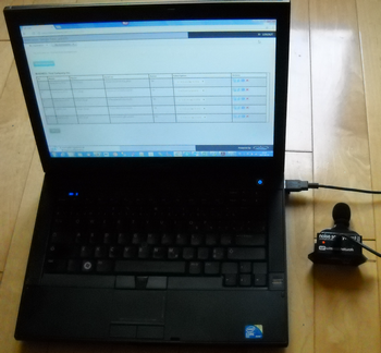
| 2. | Next you connect your instrument to the USB port on your Personal Computer. Again, for more details on that topic, please refer to the "Getting Started" chapter for your Instrument User's Manual. See table above. |
| 3. | Then you start the Instrument Manager program. If your are not familiar with the Instrument Manager, you should read the following: |
Click on the Instrument Manager icon on your desktop panel or under the Windows "Start" button.
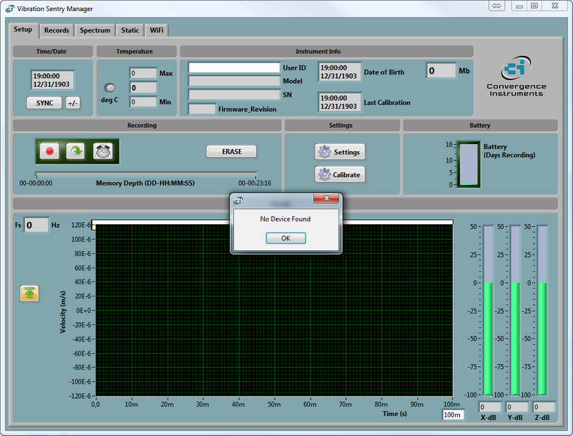
At opening of the Instrument Manager, if no instrument is connected, you should see a dialogue box similar to the following on your display.
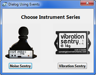
From this dialog box you can select which instrument model you want to work with.
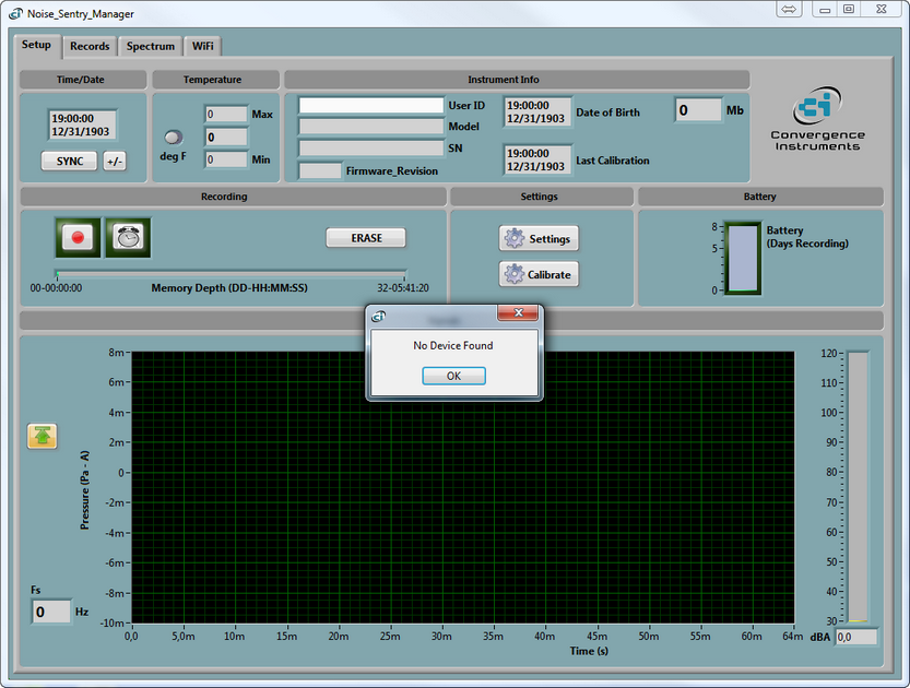
You will be notified by the Instrument Manager via a "No Device Found" pop-up window.
With no device found, the Manager will only allow you to load an instrument specific wlg file. All other tabs will be greyed. See following screen captures of the Instrument Manager.
WARNING: The Instrument Manager would normally generate an error message, or will not load the file without telling you so, if you try to open a wlg file formatted for another instrument model. If your Instrument Manager is open for a Noise Sentry, make sure your are loading a Noise Sentry instrument related wlg file. If your Instrument Manager is open for a Vibration Sentry, make sure your are loading a Vibration Sentry instrument related wlg file. Using a Vibration Sentry instrument related wlg file when the Instrument Manager is configured for a Noise Sentry instrument will generate an error message for a corrupted file.
Prior to loading the wlg file:
After loading the wlg file:
|
you will be notified by the Instrument Manager with a "No Device Found" pop-up window.
When that occurs and your intent is to configure your Noise Sentry instrument:
| 1. | First click on the  "OK" button and the Instrument Manager program will open with limited functionality. "OK" button and the Instrument Manager program will open with limited functionality. |
| 2. | Make sure the device is well connected to your USB port. Troubleshoot if necessary. Go back to step 2 of "In Depth" instructions. You can find answers to your questions by reading the following chapters in your Instrument User's Manual: |
or:
|
|
You will be notified by the Instrument Manager via a "No Device Found" pop-up window.
With no device found, the Manager will only allow you to load an instrument specific wlg file. All other tabs will be greyed. See following screen captures of the Instrument Manager.
WARNING: The Instrument Manager would normally generate an error message, or will not load the file without telling you so, if you try to open a wlg file formatted for another instrument model. If your Instrument Manager is open for a Noise Sentry, make sure your are loading a Noise Sentry instrument related wlg file. If your Instrument Manager is open for a Vibration Sentry, make sure your are loading a Vibration Sentry instrument related wlg file. Using a Vibration Sentry instrument related wlg file when the Instrument Manager is configured for a Noise Sentry instrument will generate an error message for a corrupted file.
Prior to loading the wlg file:
After loading the wlg file:
|
you will be noticed by the Instrument Manager with a "No Device Found" pop-up window.
When that occurs and your intent is to configure your Vibration Sentry instrument:
| 1. | First click on the "OK" button and the Instrument Manager program will open with limited functionality. |
| 2. | Make sure the device is well connected to your USB port. Troubleshoot if necessary. Go back to step 2 of "In Depth" instructions. You can find answers to your questions by reading the following chapters in your Instrument User's Manual: |
or:
|
|
|
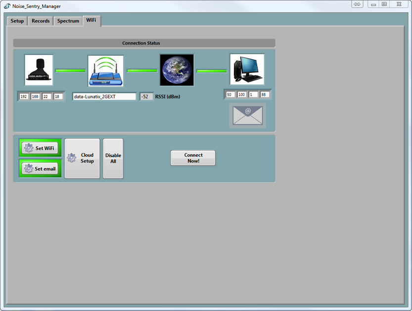
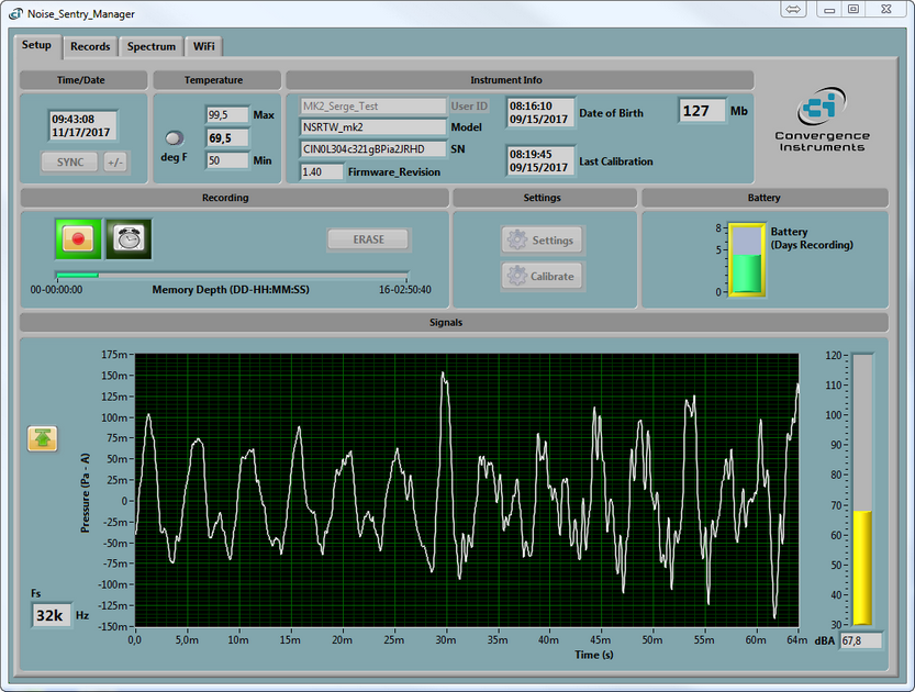
At opening of the Instrument Manager, if a Noise Sentry instrument is connected to the USB port, than the Instrument Manager will detect the model of the instrument and open with the appropriate Instrument Manager configuration:
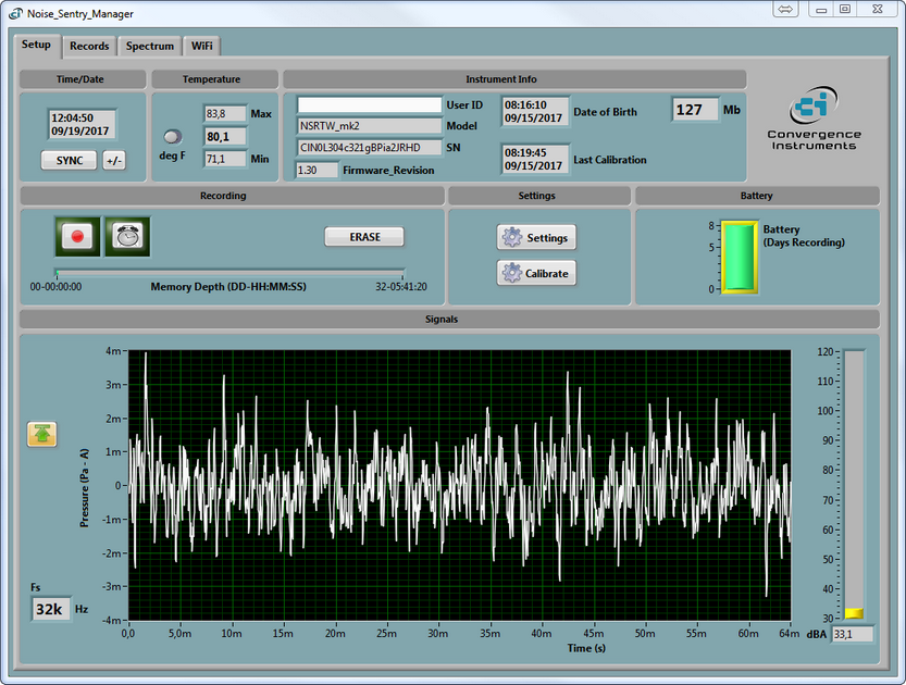
Note: All tabs are active. All available information about the instrument is loaded from the USB port, and the real time data is read from the instrument.
Note: Screen Captures published in this section of the Web Help are examples given for the Noise Sentry mk2 WiFi™ instrument. If you are using a different instrument, forms and Instrument Manager content might differ a little bit from those shown.
| 1. | Your Instrument Manager will always open showing the "Setup" page. If the instrument is unknown to the Instrument Manager, the "User ID" field will be blanked. The "Model" and "SN" are read from the non-volatile memory on the device at the moment of connection. More details on the "Setup" tab page and fields can be found in the following sub-chapter: |
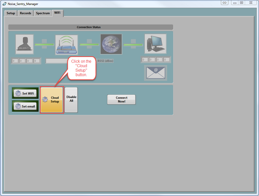
| 2. | Then you click on the "WiFi" tab to configure your instrument and its related connections and e-mail parameters. If you are not familiar with the vocabulary, the meaning of the parameters that need your attention or the WiFi™ concepts, we suggest that you give a look at sub-chapter: |
You will also find useful information on Access Points, Servers, E-mail setups and Alarms in same section.
Under the "WiFi" tab you should see the "Connection Status" box and control buttons. We will now describe the sequence of actions you must do to install your instrument perfectly on your first try.
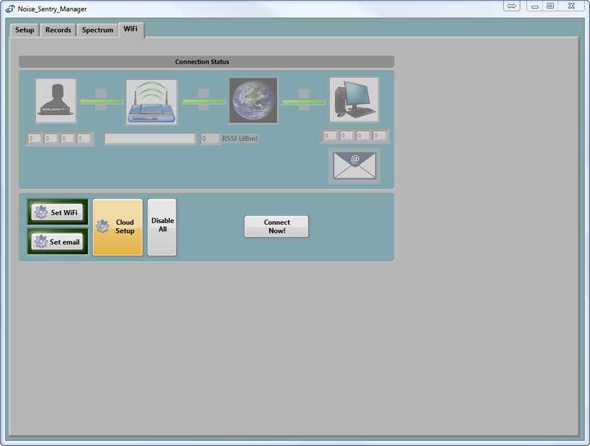
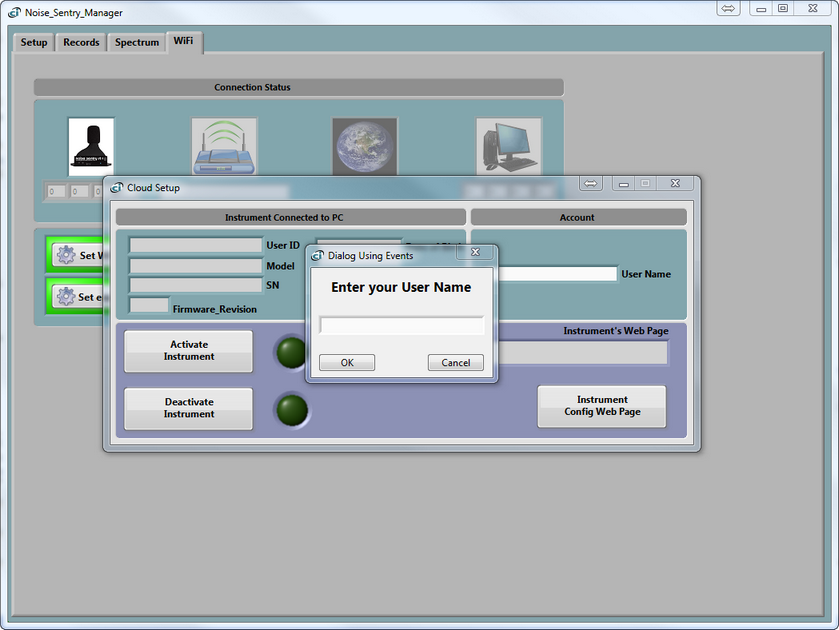
| ❖ | The "Set WiFi" and "Set email" buttons are used in manual mode only. To ease the instrument's configuration process, you simply click on the "Cloud Setup" button. |
"Set WiFi":
"Set email":
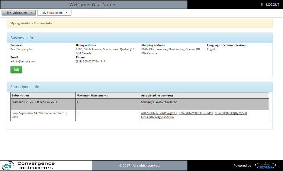
| ❖ | You are prompted to enter your "User Name". That is the one you received in an e-mail addressed to you by noreply@cidatasolutions.com and containing your credentials. It was sent to you when you bought a subscription while you were shopping on the https://www.convergenceinstruments.com/shop Web Store. Type this "User Name" and then click on the "OK" button. That information is mandatory to create the instrument's information form and later access your CIDataSolutions™ Business Account. |
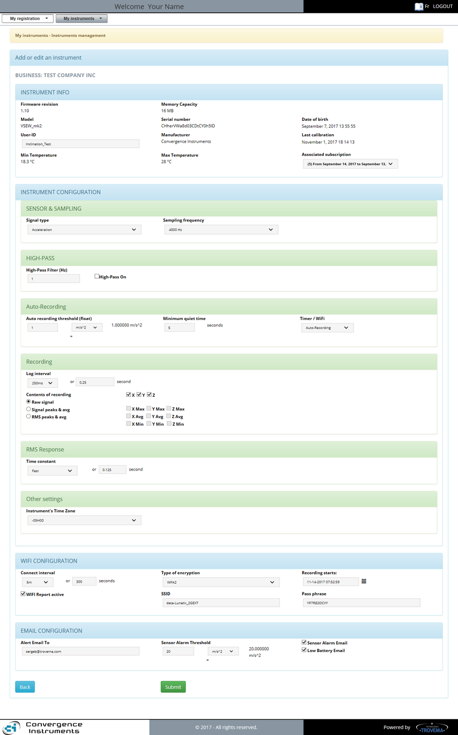
| ❖ | Your default Internet browser is launched automatically by the Instrument Manager program, with the credentials for your CIDataSolutions™ secured account. The Web application opens, landing on the "My Instruments - Instruments management" configuration form, in edit mode, for the specific instrument connected to your computer's USB port. |
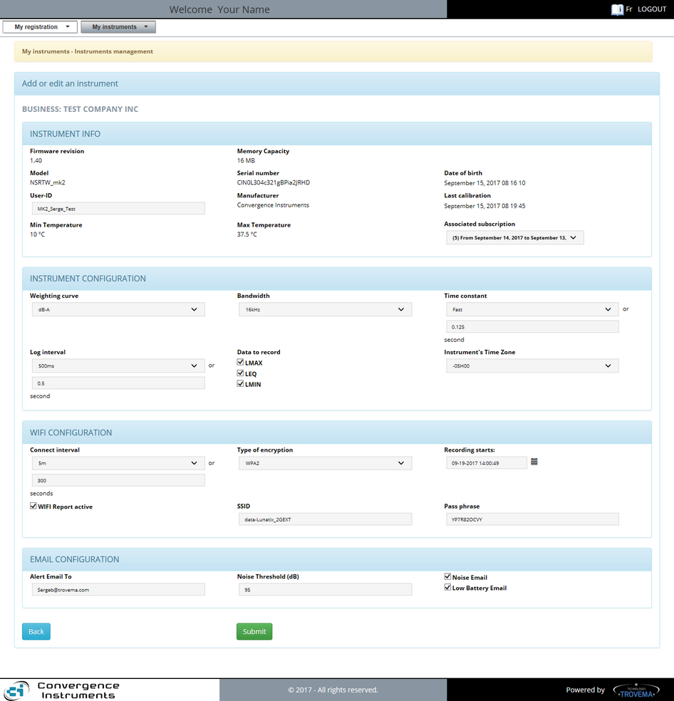
| ❖ | Edit and/or modify all fields available in this form. If you are not confident of the content, it does not really matter for now because you will be able to change those values later. What is important for now is that all fields be filled. |
| ❖ | Your CIDataSolutions™ "User Name" is shown inside the top grey banner. |
| ❖ | Below that grey banner you will notice two tabs that include all the tools you need to do your work. Do not open them for now, we will look at them in details in another topic. |
| ❖ | Inside the tan banner below the tabs, you are shown the section you are in: that is the "Instrument management" under the "My instrument" tab. That is also the reason why the associated tab is greyed. |
| ❖ | The next blue banner informs you on what this form is used for: "Add or edit an instrument". |
| ❖ | Inside this form you are shown the name under which your business subscription was registered to: "BUSINESS: Your Business Name". |
| ❖ | This is followed by four sections inside the instrument's configuration form and they are followed by two "Action buttons". We will now guide you through the fields for each of these sections. |
 Configuring a Noise Sentry instrument: Configuring a Noise Sentry instrument:
The "New instrument" form is launched by Instrument Manager to "Add" a new instrument or "Edit" the configuration for an instrument that is already installed.
We will now guide you through the details of the fields inside each section of the Noise Sentry Instruments Configuration form.
Note: Screen Captures published in this section of the Web Help are examples given for the Noise Sentry mk2 WiFi™ instrument. If you are using a different instrument, forms and Instrument Manager content might differ a little bit from those shown.
Edit and/or modify all fields available in this form. If you are not certain of the content, it does not really matter for now because you will be able to change those values later. What is important for now is that all fields are filled.
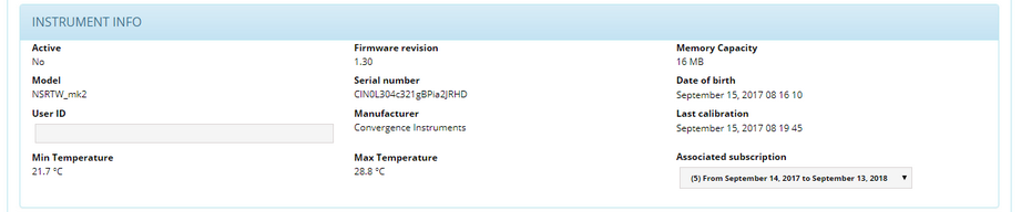
| 1. | "Active" status field: Should be "No" for now. Once we "Activate" the instrument, this field is automatically updated. |
| 2. | "Firmware revision" field: that is the revision of the firmware installed inside your instrument. This field is updated automatically when the Instrument Manager updates the firmware inside the instrument. |
| 3. | "Memory Capacity" field: That is the amount of memory available inside your instrument for data recording. |
| 4. | "Model" field: That is the model name found inside the non volatile memory of your instrument. |
| 5. | "Serial number" field: It is the production serial number of the instrument. It is not a batch number because the related IP address must be unique to each instrument. |
| 6. | "Date of birth" field: The date-time when the instrument was tested successfully after its production. |
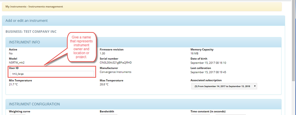
| 7. | "User-ID" field: This field you should use to give your instrument a name that makes it possible to easily locate it or recognize it among all your other instruments of the same brand or model. The User-ID is written to non-volatile memory, so it is retained even in the event of a reset or battery failure. |
| 8. | "Manufacturer" field: Must always be Convergence Instruments for genuine products. |
| 9. | "Last calibration" date field: Either the first calibration date after its production or the date the instrument was last calibrated using the Instrument Manager's "Calibrate" function found in the "Setup" tab of the program. |
| 10. | "Min Temperature" field: The minimum temperature value reached inside your instrument since it was put to work or reset. |
| 11. | "Max Temperature" field: The maximum temperature value reached inside your instrument since it was put to work or reset. |
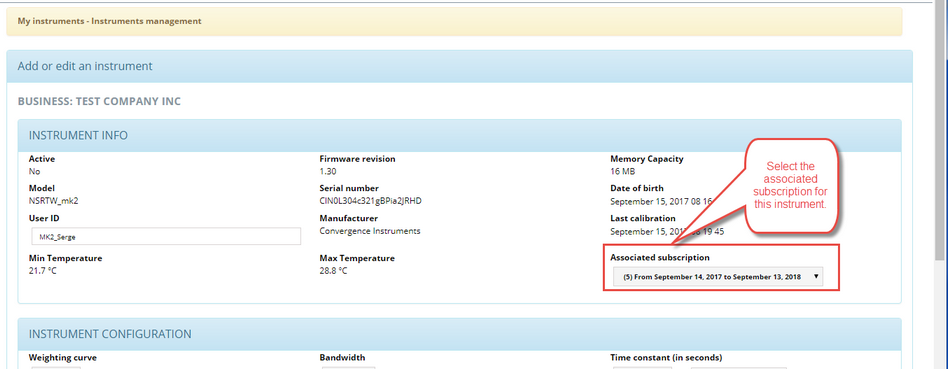
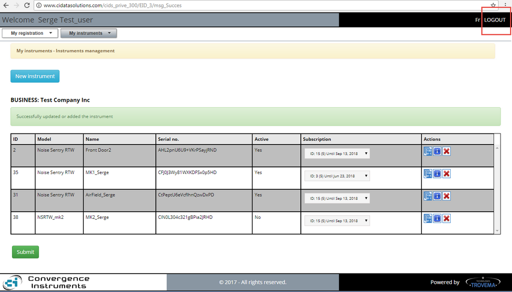
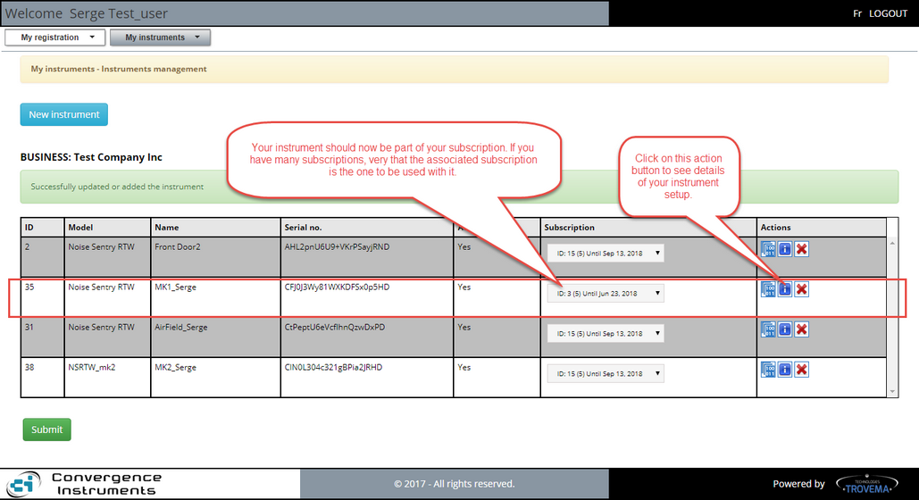
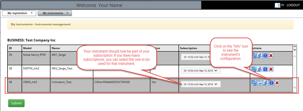
| 12. | "Associated subscription" field: The subscription you assigned last to your instrument. You can have many subscriptions, each a predetermined number of instruments that are "Active" at a time. You can manage this assignment by selecting which subscription to associate your instrument with. All active subscriptions are made available when clicking on the down arrow of the selection box. |
|
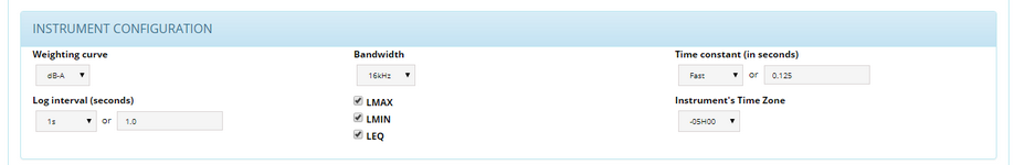
| 1. | "Weighting curve" field: Units you want your recorded values be converted to. Choices are: dB-A, dB-C, dB-Z. Use this selector to choose the weighting curve. The default is dB-A, which approximates the sensitivity of human hearing. |
| 2. | "Bandwidth" field: Bandwidth for the tracked signal. Choices are: 16kHz, 24kHz. |
| 3. | "Time constant" fields: Time constant for the tracked signal. When calculating the L-min and L-max levels, the instantaneous RMS levels are first low-pass-filtered with an adjustable time constant. |
A shorter time constant should be chosen to be able to track rapid changes. Otherwise the measurements will be smoothed out. On the other hand, when the RMS levels are slowly varying, a longer time constant will provide more precise values.
Typical fast time constants are 125 ms and under. An extra fast time constant of 35 ms is sometimes used to capture L-max on very short transients.
Typical slow time constants are 1s and over.
Note: The time constant is not used for the calculation of Leq. In that case, the sound energy is averaged linearly over the specified log interval.
| 4. | "Log interval" fields: The log interval defines the time between two successive recorded points. When recording, the L-min, L-max and Leq are reset at the beginning of each log interval. Then the instrument observes the signals for the duration of the log interval, and updates the L-min, L-max and Leq accordingly. At the end of the log interval the selected levels are written to memory. Then the next log interval is started… and so on until the recording is stopped or the memory is exhausted. |
The log interval can be adjusted from 125 ms (1/8th s) to 2 H in increments of 125 ms.
Note: The amount of memory consumed is inversely proportional to the log interval. The "Memory Capacity" indicator in the above "INSTRUMENT INFO" section automatically calculates the overall recording time as a function of the selection.
| 5. | "Statistics selector" fields: The statistics selector specifies the type of statistic to record. To select a statistic, simply press on the corresponding green indicator to light it up. By default, all statistics (L-min, L-max and Leq) are selected. The amount of memory consumed while recording is proportional to the number of statistics selected. The Memory-Depth indicator in the Setup panel automatically calculates the total recording time as a function of the selection. |
| 6. | "Instrument's Time Zone" field: You can set the time zone of the physical location of your instrument. This value will be used to construct the time scale axis on the graphs. |
|
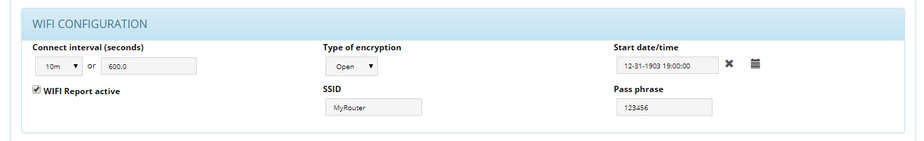
| 1. | "Connect Interval (seconds)" field: |
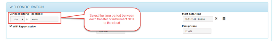
That would represent the rate at which you want the data recording being transferred to your CIDataSolutions™ account.
Possible values are: 2 minutes to 24 hours.
| 2. | "Type of encryption" field: |
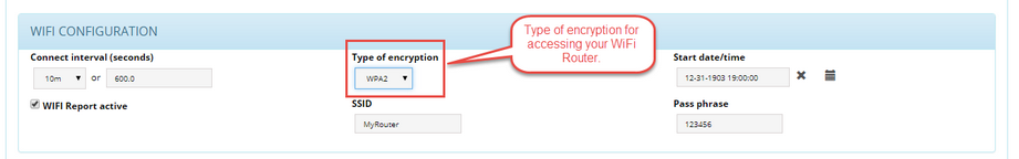
That is the type of encryption used with your local server.
Possible values are: Open, WEP, WPA, WPA2.
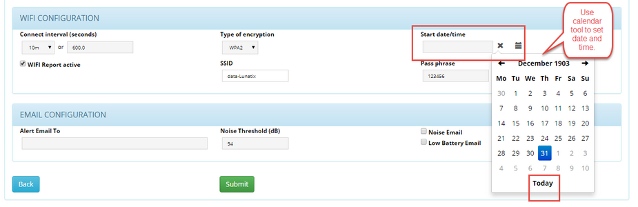
| 3. | "Start date/time" field: |
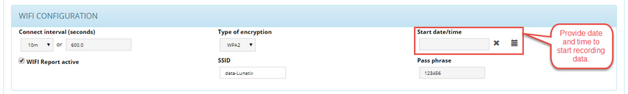
That is the moment you want your instrument start the recording of the data and later connect with your server. It is mandatory to set that date correctly whenever you initiate Instrument's configuration process. If you want the recording to start now, please select a good date and past time by a few minutes.
Possible values are: 12-01-1903 00:00:00 to ... Normally: "Today" and "Now".
Make good usage of the Calendar tool!
| 4. | "WiFi™ Report active" check-box: |
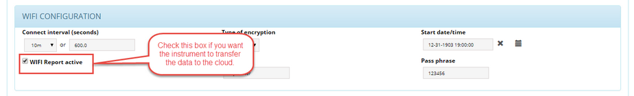
This check-box must be checked when you want your instrument to start recording.
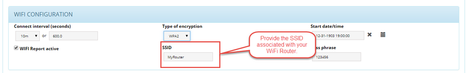
To make the communications work between your instrument and your computer, you must provide the SSID of your router.
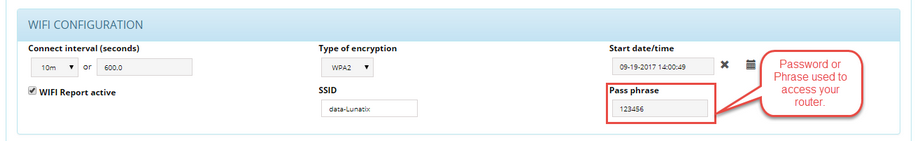
The "Pass phrase" is the secret identification to be accepted by your router when initiating communications through your router, the one with the associated "SSID".
|
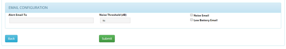
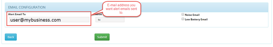
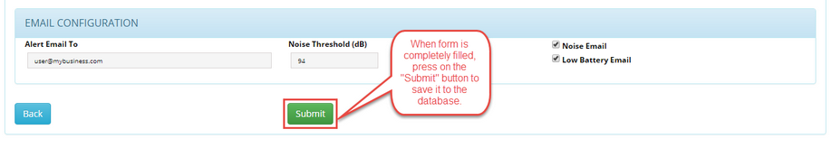
| 1. | "Alert Email To" field: This is the email address to be used with this particular instrument. |
| 2. | "Noise Threshold (dB)" field: This is the trigger point to be reached, while the instrument is recording, before sending a "Noise Email". |
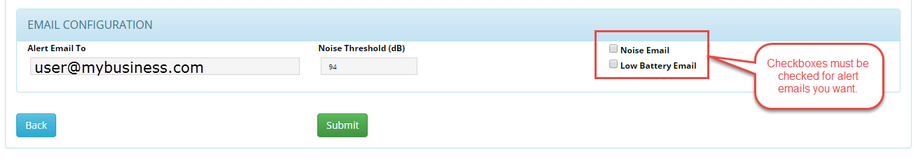
| 3. | "Noise Email" check-box: You must check that box if you want Noise Alert emails be sent to the above email address. |
| 4. | "Low Battery Email" check-box: You must check that box if you want Low Battery Alert emails be sent to the above email address. The trigger point is set by design at a point where the instruments would not be able to do his regular duties. |
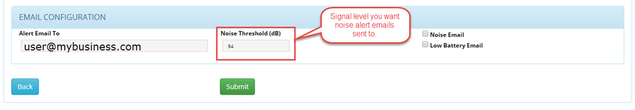
When the instruments is set with a Sound/Noise threshold, if the noise level reaches this threshold, the instrument sends the information to the user responsible for receiving such alarms. The email address must previously be set for that person to be reached. More details on that subject are given in chapter.
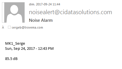
Noise Sentry RT-W (mk1 instrument) example email:
Noise Sentry RT-W (mk2 instrument) example email:
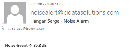
In both cases, the email contains the instrument's nick name, the date and time the event occurred, and the noise level reached at that time (see email header for date and time).
|
|
| 6. | After you have filled the "Instrument Information" form on the CIDataSolutions™ web page, which was automatically loaded by the Instrument Manager program, you simply click on the  "Submit" button to save the instrument's configuration to the database. "Submit" button to save the instrument's configuration to the database. |
| 7. | Then come back to the Instrument Manager window, make sure you are with the  "WiFi" page. "WiFi" page. |
| 8. | There you click on the  "Activate Instrument" button to finalize the installation. "Activate Instrument" button to finalize the installation. |
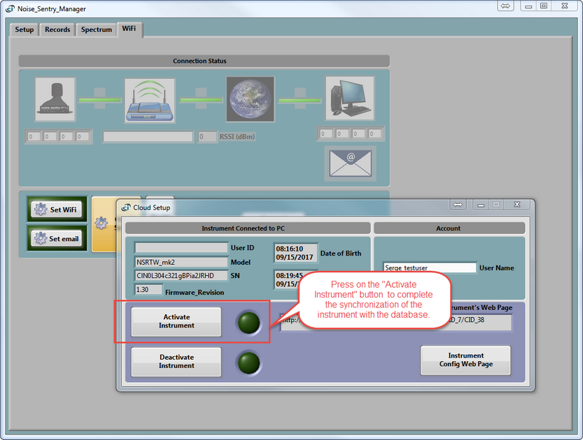
Note: If the instrument was already "Active", you must click on the  "Deactivate Instrument" button first, later followed by "Deactivate Instrument" button first, later followed by  "Activate Instrument" to transfer the updated parameters to your instrument. That would synchronize your number of active instruments with your subscription. If anything went wrong with this process, give a look at chapter: "Activate Instrument" to transfer the updated parameters to your instrument. That would synchronize your number of active instruments with your subscription. If anything went wrong with this process, give a look at chapter:
of your Instrument Manager User's Manual.
| • | You can also try the following: Click on the  "Setup" Tab of your Manager. "Setup" Tab of your Manager. |
| • | Stop the recording of the statistics with a click on the  "Record" Button. The background colour should turn to white. "Record" Button. The background colour should turn to white. |
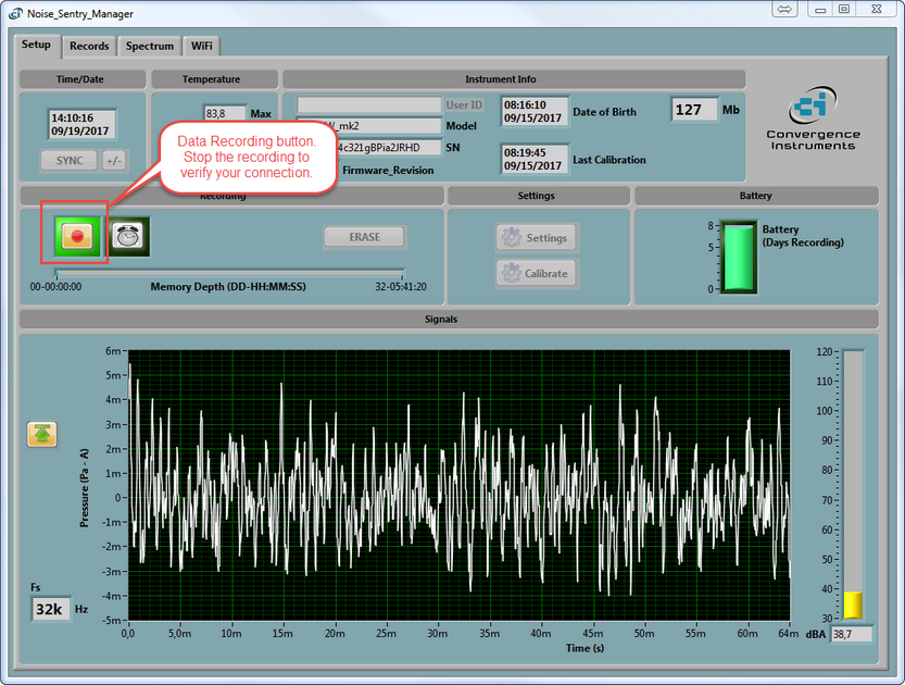
Go back to step 7 above.
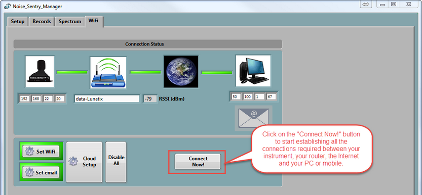
| 9. | You now should verify your connection with a simple click on the  "Connect Now!" button. This will test the overall integrity of the connectivity. "Connect Now!" button. This will test the overall integrity of the connectivity. |
| 10. | Your CIDataSolutions™ session is still active. At this point you need to "Logout" of your session. The  button is located at top right corner position of the cidatasolution window in your browser. button is located at top right corner position of the cidatasolution window in your browser. |
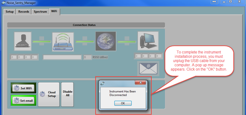
| 11. | You have just completed the configuration process. You can now unplug the instrument from the USB Port. The Instrument Manager will show a "Pop-Up" window with the following message: |
| 12. | Before you deploy in the field, it would be a good idea that you give a look at instrument's activity with your cidatasolutions Web Application. |
|
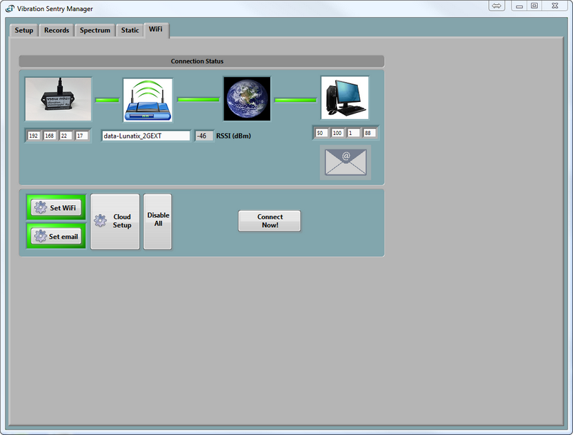
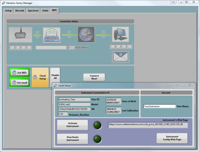
At opening of the Instrument Manager, if a Vibration Sentry instrument is connected to the USB port, than the Instrument Manager will detect the model of the instrument and open with the appropriate Instrument Manager configuration:
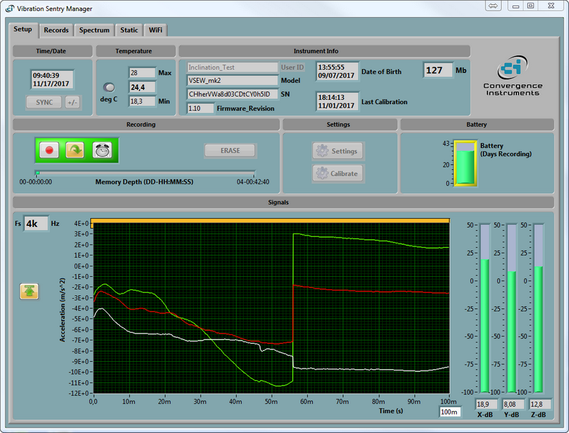
Note: All tabs are active. All available information about the instrument is loaded from the USB port, and the real time data is read from the instrument.
Note: Screen Captures published in this section of the Web Help are examples given for the Vibration Sentry mk2 WiFi™ instrument. If you are using a different instrument, forms and Instrument Manager content might differ a little bit from those shown.
| 1. | Your Instrument Manager will always open showing the "Setup" page. If the instrument is unknown to the Instrument Manager, the "User ID" field will be blanked. The "Model" and "SN" are read from the non-volatile memory on the device at the moment of connection. More details on the "Setup" tab page and fields can be found in the following sub-chapter: |
| 2. | Then you click on the "WiFi" tab to configure your instrument and its related connections and e-mail parameters. If you are not familiar with the vocabulary, the meaning of the parameters that need your attention or the WiFi™ concepts, we suggest that you give a look at sub-chapter: |
You will also find useful information on Access Points, Servers, E-mail setups and Alarms in same section.
Under the "WiFi" tab you should see the "Connection Status" box and control buttons. We will now describe the sequence of actions you must do to install your instrument perfectly on your first try.
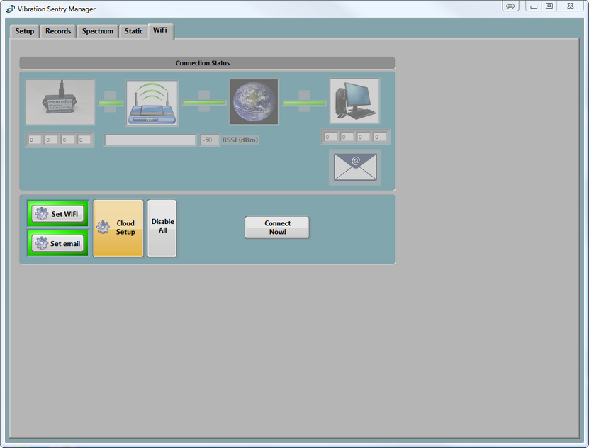
| ❖ | The "Set WiFi" and "Set email" buttons are used in manual mode only. To ease the instrument's configuration process, you simply click on the "Cloud Setup" button. |
"Set WiFi":
"Set email":
| ❖ | You are prompted to enter your "User Name". That is the one you received in an e-mail addressed to you by noreply@cidatasolutions.com and containing your credentials. It was sent to you when you bought a subscription while you were shopping on the https://www.convergenceinstruments.com/shop Web Store. Type this "User Name" and then click on the "OK" button. That information is mandatory to create the instrument's information form and later access your CIDataSolutions™ Business Account. |
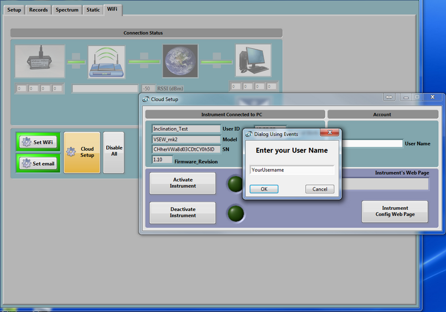
| ❖ | Your default Internet browser is launched automatically by the Instrument Manager program, with the credentials for your CIDataSolutions™ secured account. The Web application opens, landing on the "My Instruments - Instruments management" configuration form, in edit mode, for the specific instrument connected to your computer's USB port. |
| ❖ | Edit and/or modify all fields available in this form. If you are not confident of the content, it does not really matter for now because you will be able to change those values later. What is important for now is that all fields be filled. |
| ❖ | Your CIDataSolutions™ "User Name" is shown inside the top grey banner. |
| ❖ | Below that grey banner you will notice two tabs that include all the tools you need to do your work. Do not open them for now, we will look at them in details in another topic. |
| ❖ | Inside the tan banner below the tabs, you are shown the section you are in: that is the "Instrument management" under the "My instrument" tab. That is also the reason why the associated tab is greyed. |
| ❖ | The next blue banner informs you on what this form is used for: "Add or edit an instrument". |
| ❖ | Inside this form you are shown the name under which your business subscription was registered to: "BUSINESS: Your Business Name". |
| ❖ | This is followed by four sections inside the instrument's configuration form and they are followed by two "Action buttons". We will now guide you through the fields for each of these sections. |
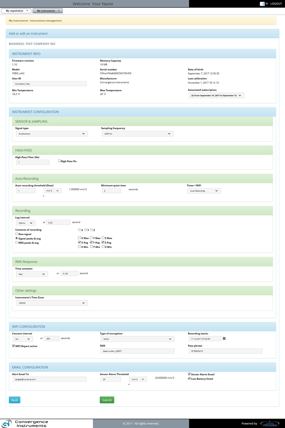
Case Vibration Sentry instrument:
The "New instrument" form is used to "Add" a new instrument or "Edit" the configuration for an instrument that is already installed.
We will now guide you through the details of the fields inside each section.
Note: Screen Captures published in this section of the Web Help are examples given for the Vibration Sentry mk2 WiFi™ instrument. If you are using a different instrument, forms and Instrument Manager content might differ a little bit from those shown.
Edit and/or modify all fields available in this form. If you are not certain of the content, it does not really matter for now because you will be able to change those values later. What is important for now is that all fields are filled.
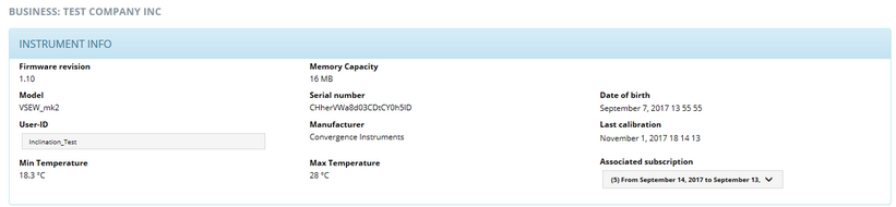
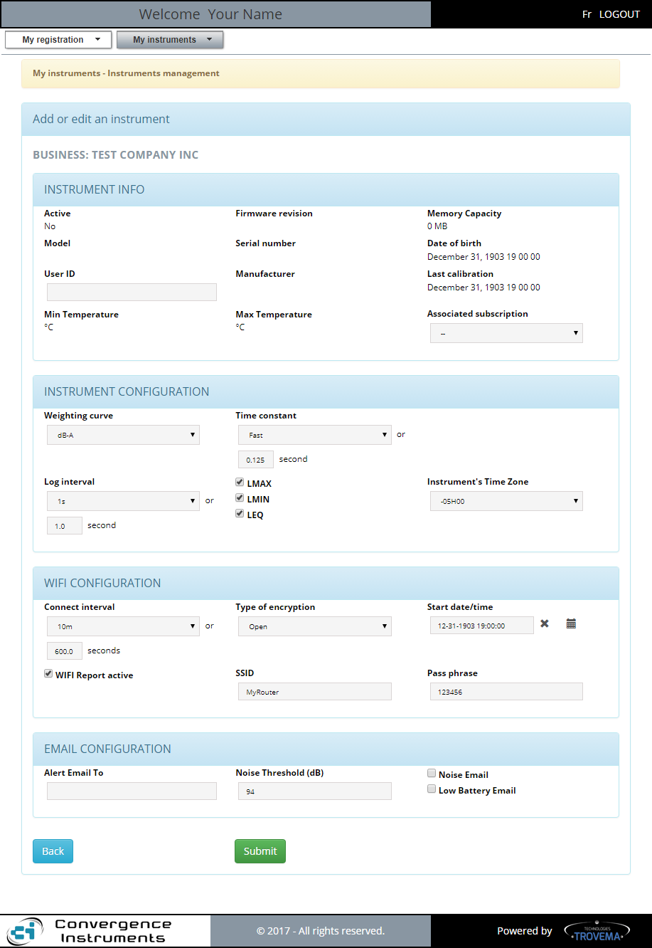
| 1. | "Firmware revision" field: that is the revision of the firmware installed inside your instrument. This field is updated automatically when the Instrument Manager updates the firmware inside the instrument. |
| 2. | "Memory Capacity" field: That is the amount of memory available inside your instrument for data recording. |
| 3. | "Model" field: That is the model name found inside the non volatile memory of your instrument. |
| 4. | "Serial number" field: It is the production serial number of the instrument. It is not a batch number because the related IP address must be unique to each instrument. |
| 5. | "Date of birth" field: The date-time when the instrument was tested successfully after its production. |
| 6. | "User ID" field: This field you should use to give your instrument a name that makes it possible to easily locate it or recognize it among all your other instruments of the same brand or model. The User-ID is written to non-volatile memory, so it is retained even in the event of a reset or battery failure. |
| 7. | "Manufacturer" field: Must always be Convergence Instruments for genuine products. |
| 8. | "Last calibration" date field: Either the first calibration date after its production or the date the instrument was last calibrated using the Instrument Manager's "Calibrate" function found in the "Setup" tab of the program. |
| 9. | "Min Temperature" field: The minimum temperature value reached inside your instrument since it was put to work or reset. |
| 10. | "Max Temperature" field: The maximum temperature value reached inside your instrument since it was put to work or reset. |
| 11. | "Associated subscription" field: The subscription you assigned last to your instrument. You can have many subscriptions, each a predetermined number of instruments that are "Active" at a time. You can manage this assignment by selecting which subscription to associate your instrument with. All active subscriptions are made available when clicking on the down arrow of the selection box. |
|
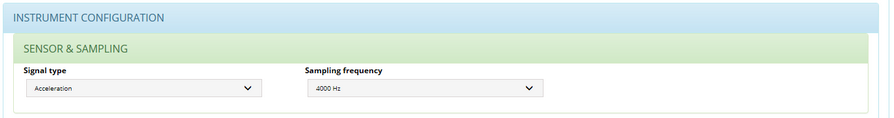
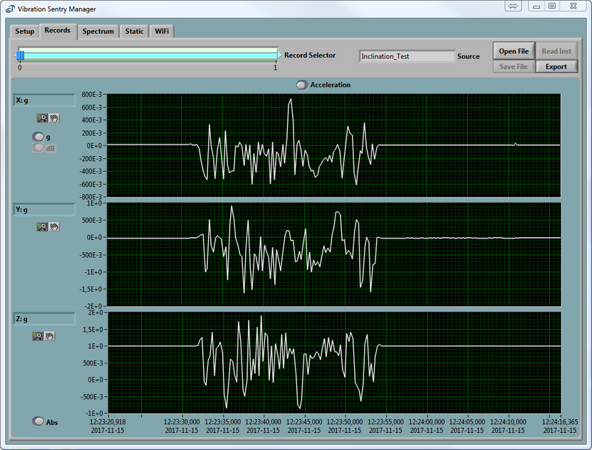
| 1. | "Signal type" selector: Type of sampling you want your instrument to perform. The choices are: Acceleration and Velocity. Inclination curves are derived from Acceleration data. |
| 2. | "Sampling frequency" selector: Adjustable Data sampling rate. Choices are: 4000 Hz, 2000 Hz, 1000 Hz, 500 Hz, 250 Hz, 125 Hz, 63 Hz, 32Hz, 16Hz, 8 Hz and 4 Hz. The power consumption while recording is roughly proportional to the sampling frequency. When recording raw signals the amount of memory consumed is proportional to the sampling frequency. The Memory-Depth indicator in the Setup panel automatically calculates the overall recording time as a function of the selection. for more details on that subject, please refer to chapter 8.3.5.1.1 Sampling Frequency of the VSEW_mk2 User's manual. |
|
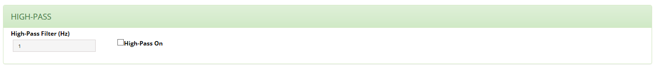
| 1. | "High-Pass Filter" field: Value field for the High-Pass Filter. The value is given in Hz. When measuring accelerations an adjustable-frequency high-pass filter can be added to the measurement path. The high-pass filter is required to measure RMS vibration levels. Otherwise the measured RMS levels would be biased by the DC component. On the other hand, inclination measurements require the measurement of the DC component, so DO NOT use the high-pass filter for inclinations. When measuring velocities, a high-pass filter is automatically placed in the signal path. The field on the left is used to adjust the cutoff frequency. Thanks to its very high resolution, the high-pass filter can be adjusted to frequencies that are extremely low relative to the sampling frequency.For more details on that subject please refer to chapter 6.5.1 Measurement of the VSEW_mk2 User's Manual. |
| 2. | "High-Pass On" checkbox: The High-Pass filter can be selected or deselected by clicking on the checkbox. |
|
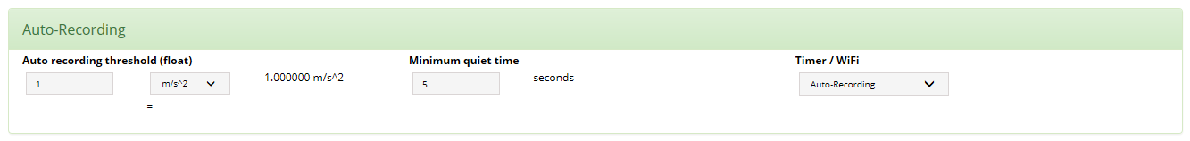
These settings adjust the trigger threshold and the inactivity period. Once the instrument is placed in Auto-Rec mode it switches between two states:
| • | Waiting for inactivity While recording, the instrument waits for inactivity. Inactivity is defined as “signal that stays below the threshold on all three axes for a time longer than the inactivity period”. |
| • | When inactivity is detected the instrument stops the ongoing recording. Therefore the inactivity time defines the minimum amount of time that the instrument will record, once triggered. The recording will keep going if the signal keeps passing the threshold while the recording is ongoing. |
| 1. | "Auto recording threshold (float)" field: Value field for triggering the recording. Waiting for activity. While in inactive mode the instrument waits for activity. Activity is defined as “signal that transitions through the threshold on at least one axis”. The signal must be below, then above the threshold to trigger the recording. When activity is detected the instrument creates a new record and starts recording. The threshold is the same on all axes. More information on that subject can be found in chapters "6.9 manual Recording" and "6.10 AutoRec recording" of the VSEW_mk2 User's Manual. |
| 2. | "Threshold units" selector: The statistic and the recording threshold can be set either in "g" or "m/s^2 when the statistic is Acceleration. Units will be "m/s" when instrument is configured for Velocity. |
| 3. | "Minimum quiet time": While recording, the instrument waits for inactivity. Inactivity is defined as “signal that stays below the threshold on all three axes for a time longer than the inactivity period”. When inactivity is detected the instrument stops the ongoing recording. Therefore the inactivity time defines the minimum amount of time that the instrument will record, once triggered. The recording will keep going if the signal keeps passing the threshold while the recording is ongoing. |
| 4. | "Timer / WiFi" selector: This control defines the action to take when the timer is engaged, or if the recording is started via WiFi™ through the server. The choices are: "Record" and "Auto-recording. Record: The recording will start once the timer has reached the specified time and date. Auto-recording: The instrument will go to Auto-Rec mode once the timer has reached the specified time and date. |
|
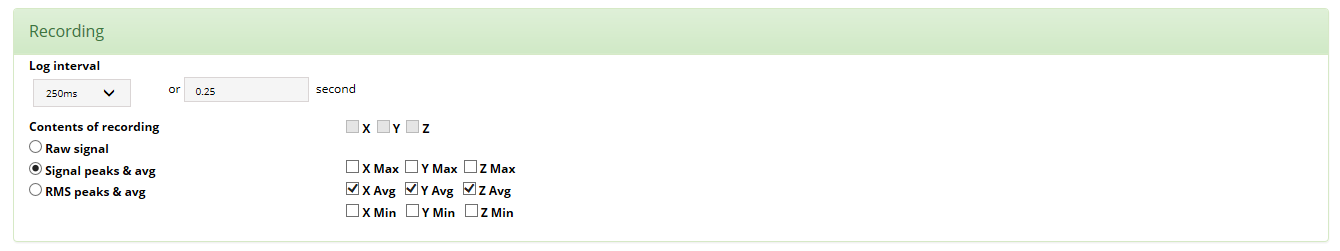
| 1. | "Log interval" selector and field: The log interval defines the time between two successive recorded points when the instrument is recording signal statistics or RMS level statistics. When recording either type of statistics the min, max and average are reset at the beginning of each log interval. Then the instrument observes the signals or levels for the duration of the log interval, and updates the min, max and averages accordingly. At the end of the log interval the selected statistics are written to memory. Then the next log interval is started… and so on until the recording is stopped or the memory is exhausted. The log interval is only relevant when recording statistics. When recording raw signals the time between two successive samples is simply the sampling period. The log interval can be adjusted from 125 ms to 2 H in increments of 125 ms. Note: When recording statistics the amount of memory consumed is inversely proportional to the log interval. The Memory-Depth indicator in the Setup panel of the Instrument Manager automatically calculates the overall recording time as a function of the selection. |
| 2. | "Content of recording" buttons and check boxes: You must first select one of the three following buttons. These buttons specify whether raw signals, signal statistics or RMS level statistics are being recorded. In either case the user must choose the axes, and optionally the types of statistics to record. To select or deselect an axis or statistic, simply press on the corresponding check boxes. Note: In order to record inclinations select “Acceleration”, then select “Signal peaks & avg” and select at least the X-avg, Y-avg and Z-avg selectors. The inclinations are calculated from those acceleration measurements. The amount of memory consumed while recording is proportional to the number of channels and statistics selected. |
| a. | "Raw signal" button: The signal (acceleration or velocity) is recorded at the sampling frequency. |
| b. | "Signal peaks & avg" button: The Signal Statistics processing captures the min, max and average of the acceleration or velocity signal over an adjustable recording (log) interval. For each new interval the statistics are cleared, then the statistics are updated during the course of the interval, then at the end of the interval the statistics are recorded, and a new interval is started. |
| c. | "RMS peaks and avg" button: the RMS-Level signal is squared to calculate the instantaneous power. The instantaneous power is low-pass-filtered with an adjustable time constant to produce an average. A short time constant provides an average that is capable of tracking fast transients, while a longer time constant provides a smoother and less noisy average. A typical fast time constant is around 100ms. While a typical long time constant is around 1s. Finally the square-root of the power is taken to present RMS vibration or velocity levels. The RMS vibration levels can be displayed in linear or dB scale. |
| d. | Axes check boxes: From the "Signal type" and the previous selection, the maximum recording content for the three axes is automatically checked. You can reduce the recording to the axes you want and Max, Avg, Min values you want. |
|
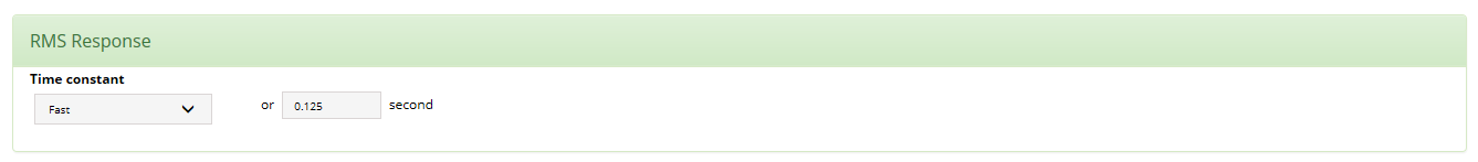
| 1. | "Time constant" selector and field: If recording RMS levels, select the time constant used to smooth the measured levels for min and max. Choose a time constant around 125 ms to be able to detect short transients. Choose a time constant around 1s to provide cleaner and more stable RMS levels. Or adjust to another value, as required by the application. The selector choices are: "Impulse" = 0.035 s, "Slow" = 1.0 s, "Fast" = 0.125 s and "--" = your value. |
|
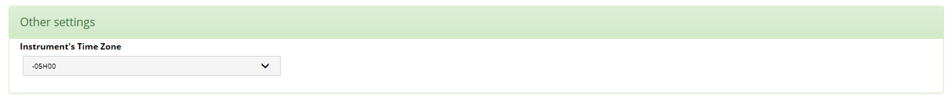
| 1. | "Instrument's Time Zone" selector: The instrument is normally setup with the UTC. If you want the records to be adjusted to the Local Time of your instrument, you must specify it by selecting the proper time zone. For instance New Yorc city Time Zone is GMT-4H00 during Summer Time and GMT-5H00 during Winter Time. |
|
|
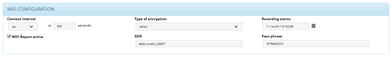
| 1. | "Connect Interval" selector and field: That would represent the rate at which you want the recording data being transferred to your CIDataSolutions™ account on the Cloud |
Possible values are: 2 minutes to 24 hours.
| 2. | "Type of encryption" selector: That is the type of encryption used with your local server. Possible values are: Open, WEP, WPA, WPA2. |
| 3. | "Recording starts" Date and time field with a calendar tool  : That is the moment you want your instrument to start recording the data. It is mandatory to set that date correctly whenever you initiate Instrument's configuration process. Possible values are: 12-01-1903 00:00:00 to ... Normally: "Today" and "Now". Make good usage of the Calendar tool! : That is the moment you want your instrument to start recording the data. It is mandatory to set that date correctly whenever you initiate Instrument's configuration process. Possible values are: 12-01-1903 00:00:00 to ... Normally: "Today" and "Now". Make good usage of the Calendar tool! |
| 4. | "WiFi™ Report active" check-box: This check-box must be checked when you want your instrument to transfer the data to the Cloud after it started recording. |
| 5. | "SSID" field: To make the communications work between your instrument and your computer, you must provide the SSID of your router. |
| 6. | "Pass phrase" field: The "Pass phrase" is the secret identification to be accepted by your router when initiating communications through your router, the one with the associated "SSID". |
|
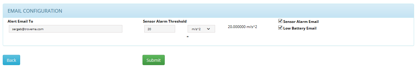
| 1. | "Alert Email To" field: This is the email address to be used with this particular instrument. |
| 2. | "Sensor Alarm Threshold" selector and field: This is the trigger point to be reached, while the instrument is recording, before sending a "Vibration Alarm Email". |
| 3. | "Sensor Alarm Email" check-box: You must check that box if you want Vibration Alert emails be sent to the above email address. |
| 4. | "Low Battery Email" check-box: You must check that box if you want Low Battery Alert emails be sent to the above email address. The trigger point is set by design at a point where the instruments would not be able to do his regular duties. |
When the instruments is set with a Vibration threshold, if the acceleration level reaches this threshold, the instrument sends the alert to the user responsible for receiving such alarms. The email address must previously be set for that person to be reached. More details on that subject are given in chapter:
VSEW_mk2 example email:
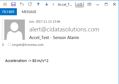
The email contains the instrument's nick name, the date and time the event occurred, and the acceleration level reached at that time (see email header for date and time).
|
|
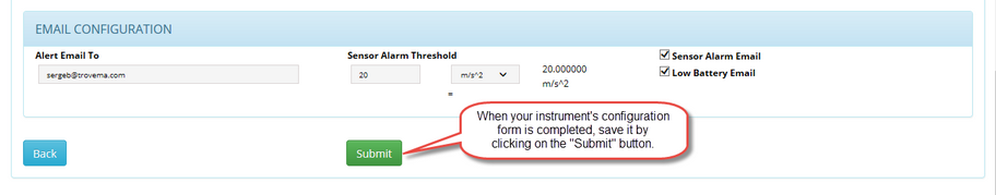
| 6. | After you have filled the "Instrument Information" form on the CIDataSolutions™ web page, which was automatically loaded by the Instrument Manager program, you simply click on the "Submit" button to save the instrument's configuration to the database. |
| 7. | Then come back to the Instrument Manager window, make sure you are with the "WiFi" page. |
| 8. | There you click on the "Activate Instrument" button to finalize the installation. |
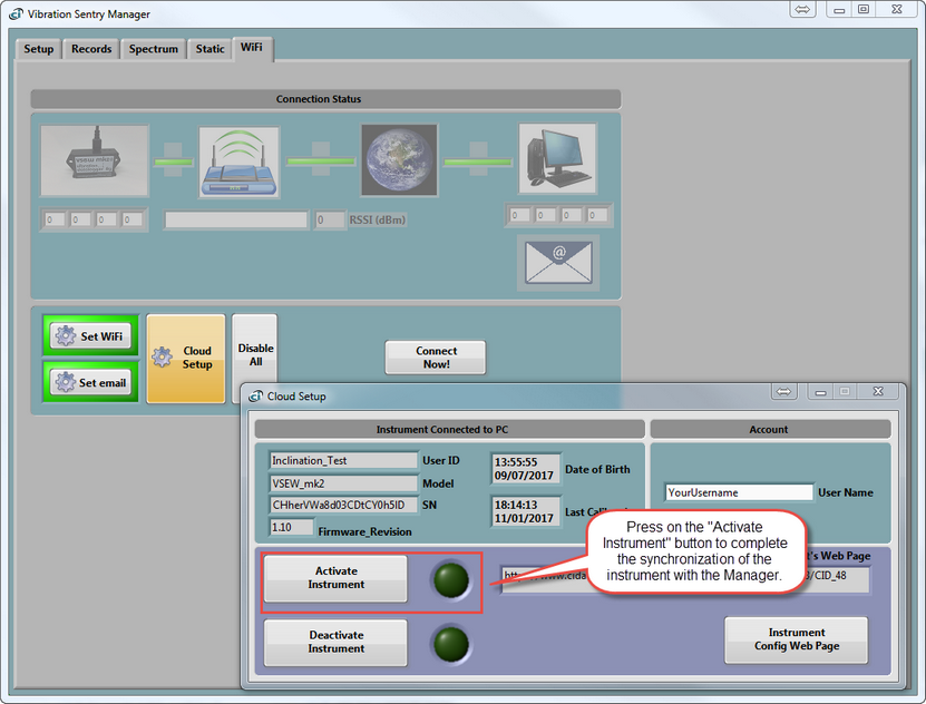
Note: If the instrument was already "Active", you must click on the "Deactivate Instrument" button first, later followed by "Activate Instrument" to transfer the updated parameters to your instrument. That would synchronize your number of active instruments with your subscription. If anything went wrong with this process, give a look at chapter:
of your Instrument Manager User's Manual.
| • | You can also try the following: Click on the "Setup" Tab of your Manager. |
| • | Stop the recording of the statistics with a click on the "Record" Button. The background colour should turn to white. |
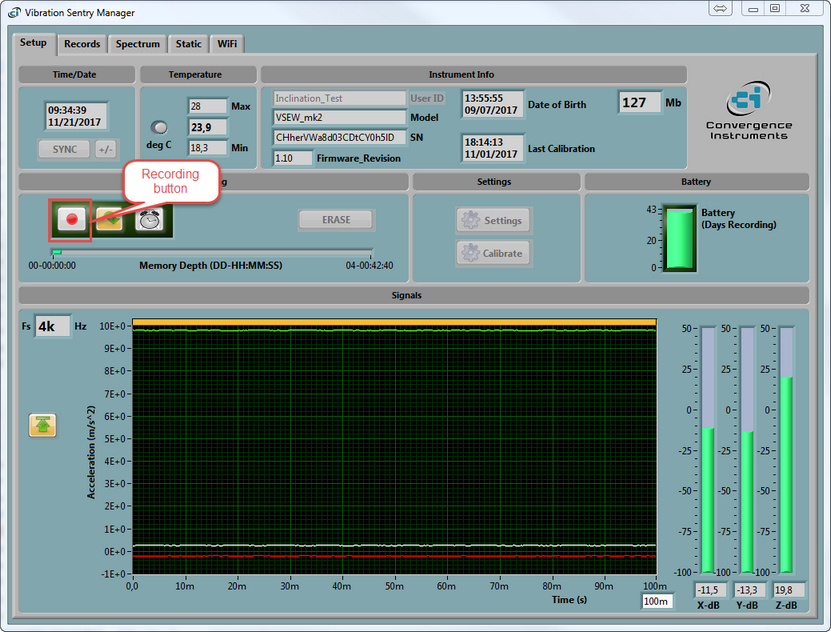
Go back to step 7 above.
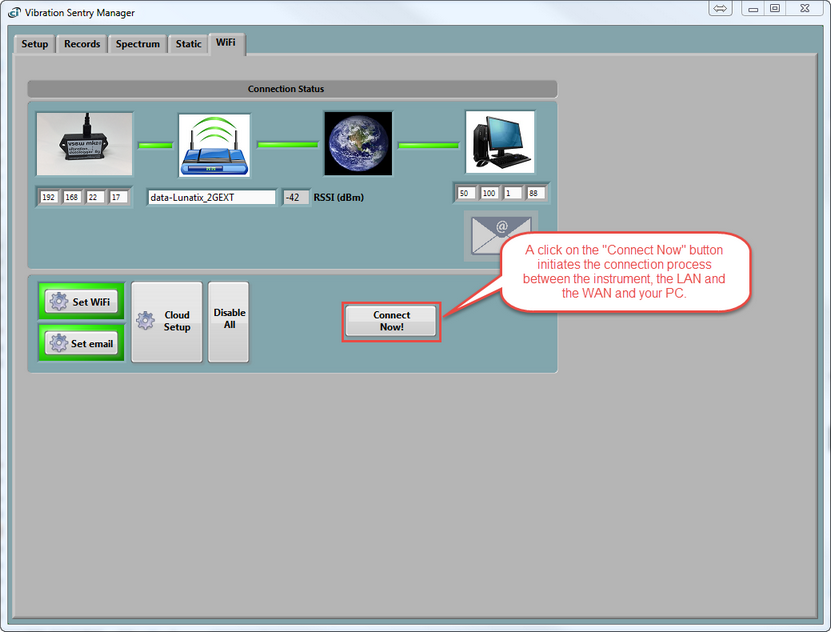
| 9. | You now should verify your connection with a simple click on the "Connect Now!" button. This will test the overall integrity of the connectivity. |
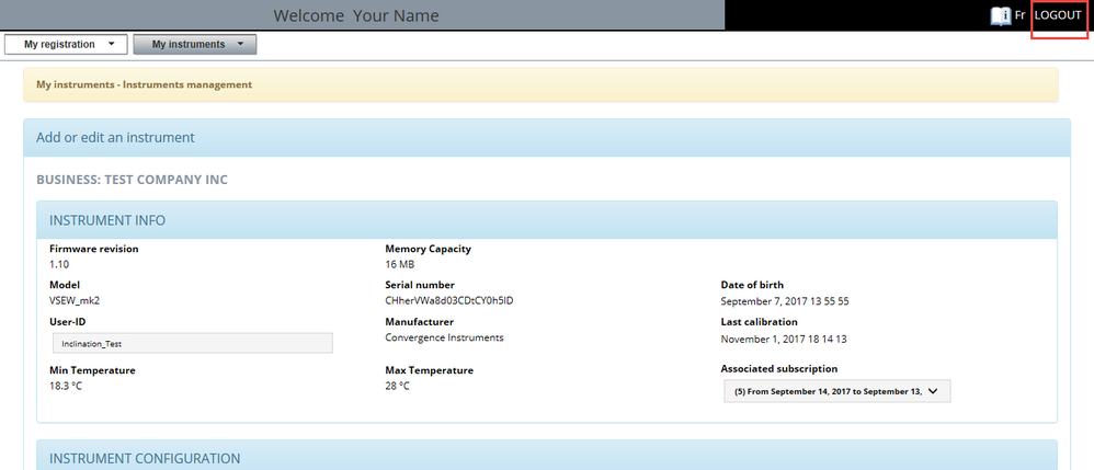
| 10. | Your CIDataSolutions™ session is still active. At this point you need to "Logout" of your session. The button is located at top right corner position of the cidatasolution window in your browser. |
| 11. | You have just completed the configuration process. You can now unplug the instrument from the USB Port. The Instrument Manager will show a "Pop-Up" window with the following message: |
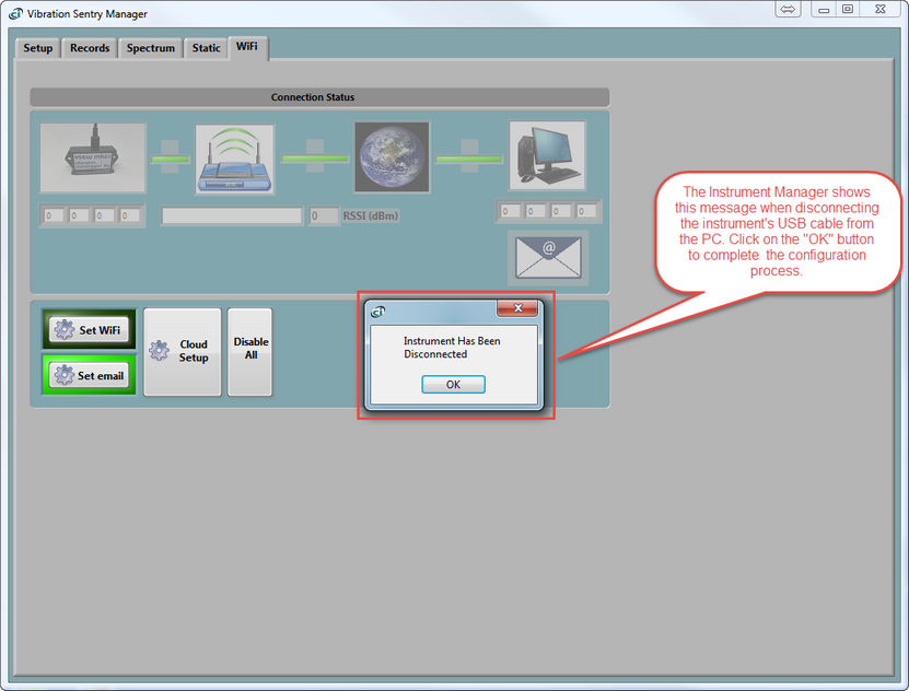
| 12. | Before you deploy in the field, it would be a good idea that you give a look at instrument's activity with your cidatasolutions Web Application. |
|
|
Congratulation!
You are all set with your instrument and ready to make good use of its recorded data.
If its your first experience with CIDataSolutions™ Web Application, your next step is to open your browser and complete your secured access to https://www.cidatasolutions.com, using your credentials (user name and temporary password).
If you are an old timer, the recorded data of the instrument you recently installed or configured is ready to work with the CIDataSolutions™ Web Application.
|
 Installation Process